Custom Hinge Selection Tool
Holes : Countersinking
See dimensional charts below.
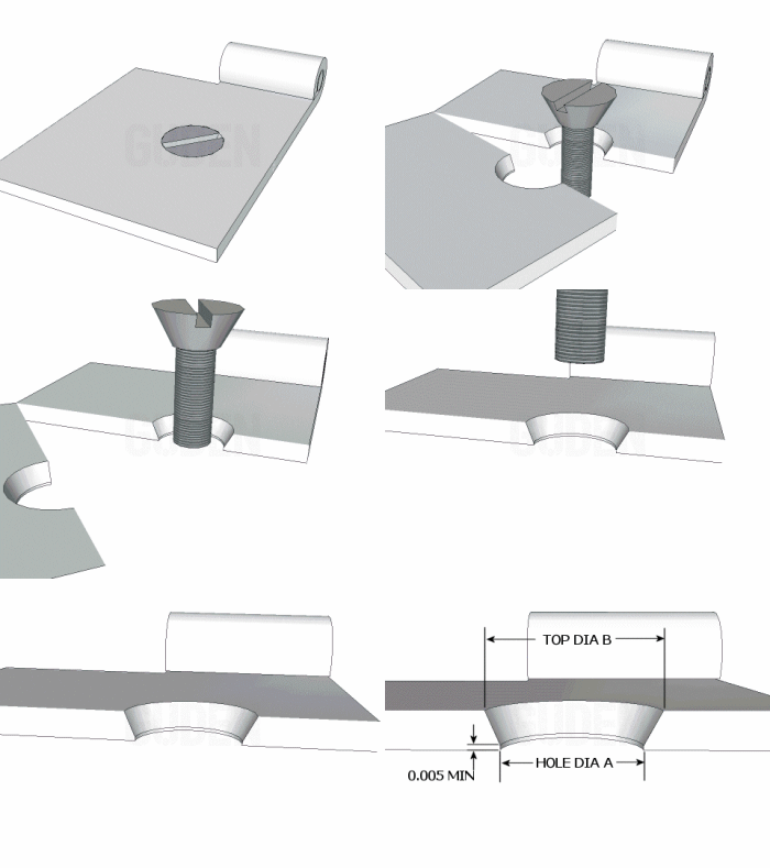
Holes
have a countersink added to them when a flat head screw or rivet will be used so that the screw head doesn't stick out above the surface of the leaf.This requirement frequently comes up with hinges because when the hinge swings closed, there is often little room for fastener heads sticking up from the surface of the hinge. It is especially true when the holes on both leaves are located directly across from each other.
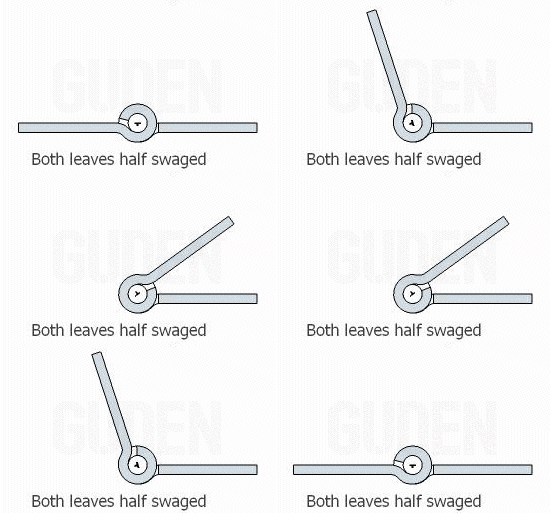
For example, on half swaged hinges, there is no space for fastener heads when the hinge closes. Countersunk holes are common in this configuration.
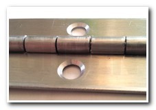
Flat head screw sizes are numbered. It is acceptable to dimension holes by this number, ex: "Hole for #8 Flat Head Screw"

You can also call out the dimensions by an angle and diameter. The most popular angle call outs are 82 and 100 degrees, but other angles are also available.
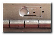
You can also call out the dimensions by upper and lower diameters.
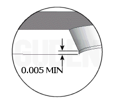
Note that it is important to design at least a small amount of material to remain uncut. If this is not provided for, the tools used to cut the countersink will raise an unacceptable burr on the backside of the hinge.
![[Countersink Diagram]](/CustomHinges/[Categories]/Holes/Countersinking/countersink.gif)
Why our hole diameter is usually greater than the body diameter
When punching a hole in sheetmetal in preparation for countersinking, we punch a hole large enough to leave a minimum of .005" at the bottom of the hole so that there is no burr formed. The diagram above demonstrates this .005" minimum. We have calculated the hole diameter required for a number of popular screw sizes and have listed the dimensions in the tables below.
Table for 82 Degree Countersinks
| Screw Size | #4 | #5 | #6 | #8 | #10 | #12 | 1/4-20 |
| Max. Head Dia. | 0.225 | 0.252 | 0.279 | 0.332 | 0.385 | 0.438 | 0.507 |
| Min. Head Dia. | 0.207 | 0.232 | 0.257 | 0.308 | 0.359 | 0.410 | 0.477 |
| Top Ctsk. Dia. | 0.216 | 0.242 | 0.268 | 0.320 | 0.372 | 0.424 | 0.492 |
| Body Dia. | 0.112 | 0.125 | 0.138 | 0.164 | 0.190 | 0.216 | 0.250 |
| Screw Size | #4 | #5 | #6 | #8 | #10 | #12 | 1/4-20 |
| Thickness | Hole Sizes Before Countersinking for 82 Degree Screws (+/-.005) | ||||||
| 0.020 | 0.1950 | 0.2220 | 0.2490 | 0.3020 | 0.3550 | 0.4060 | 0.4770 |
| 0.025 | 0.1870 | 0.2130 | 0.2400 | 0.2930 | 0.3460 | 0.4060 | 0.4680 |
| 0.030 | 0.1760 | 0.2010 | 0.2280 | 0.2810 | 0.3340 | 0.4060 | 0.4560 |
| 0.035 | 0.1660 | 0.1960 | 0.2210 | 0.2740 | 0.3280 | 0.4060 | 0.4490 |
| 0.042 | 0.1600 | 0.1870 | 0.2130 | 0.2630 | 0.3170 | 0.4060 | 0.4370 |
| 0.050 | 0.1410 | 0.1700 | 0.1960 | 0.2500 | 0.3030 | 0.3830 | 0.4240 |
| 0.060 | 0.1280 | 0.1520 | 0.1790 | 0.2320 | 0.2850 | 0.3830 | 0.4060 |
| 0.074 | 0.1250 | 0.1280 | 0.1560 | 0.2080 | 0.2630 | 0.3680 | 0.3830 |
| 0.090 | 0.1250 | 0.1280 | 0.1560 | 0.1940 | 0.2500 | 0.3360 | 0.3680 |
| 0.120 | 0.1250 | 0.1280 | 0.1560 | 0.1870 | 0.2130 | 0.3030 | 0.3120 |
| 0.179 | 0.1250 | 0.1280 | 0.1560 | 0.1870 | 0.2130 | 0.2320 | 0.3120 |
| 0.250 | 0.1250 | 0.1280 | 0.1560 | 0.1870 | 0.2130 | 0.2320 | 0.3120 |
Our standard for the diameter for the top of the countersink is to take the middle of the range for the nominal dimension with a tolerance of plus or minus .010. For example for a #8 flat head screw in .042 thick material, we would punch a .263 diameter hole and countersink to .320 (.332 plus .308 divided by 2) plus or minus .010. Any dimension for the top of the countersink from .310 to .330 would be considered within tolerance.
The hole punched in the sheet metal is designed to leave a minimum .005 wall after the countersink is complete. This will prevent burr formation on the bottom side of the sheet metal. For the example above we would punch a .263 diameter hole, although the body diameter of the screw is .164. Part of the head will extend below the surface of the sheet metal.
Table for 100 Degree Countersinks
| Screw Size | #4 | #5 | #6 | #8 | #10 | #12 | 1/4-20 |
| Max. Head Dia. | 0.231 | 0.257 | 0.283 | 0.335 | 0.387 | 0.439 | 0.507 |
| Min. Head Dia. | 0.201 | 0.227 | 0.253 | 0.305 | 0.357 | 0.409 | 0.477 |
| Top Ctsk. Dia. | 0.216 | 0.242 | 0.268 | 0.320 | 0.372 | 0.424 | 0.492 |
| Body Dia. | 0.112 | 0.125 | 0.138 | 0.164 | 0.190 | 0.216 | 0.250 |
| Screw Size | #4 | #5 | #6 | #8 | #10 | #12 | 1/4-20 |
| Thickness | Hole Sizes Before Countersinking for 100 Degree Screws (+/-.005) | ||||||
| 0.020 | 0.1870 | 0.2130 | 0.2490 | 0.3020 | 0.3460 | 0.4060 | 0.4770 |
| 0.025 | 0.1870 | 0.2130 | 0.2320 | 0.2930 | 0.3460 | 0.4060 | 0.4680 |
| 0.030 | 0.1760 | 0.1960 | 0.2210 | 0.2740 | 0.3360 | 0.3830 | 0.4560 |
| 0.035 | 0.1600 | 0.1870 | 0.2130 | 0.2630 | 0.3120 | 0.3680 | 0.4370 |
| 0.042 | 0.1410 | 0.1760 | 0.1960 | 0.2500 | 0.3130 | 0.3680 | 0.4240 |
| 0.050 | 0.1250 | 0.1280 | 0.1760 | 0.2320 | 0.2850 | 0.3360 | 0.4060 |
| 0.060 | 0.1250 | 0.1280 | 0.1560 | 0.2130 | 0.2850 | 0.3830 | 0.4060 |
| 0.074 | 0.1250 | 0.1280 | 0.1560 | 0.1870 | 0.2130 | 0.2320 | 0.3120 |
| 0.090 | 0.1250 | 0.1280 | 0.1560 | 0.1870 | 0.2130 | 0.2320 | 0.3120 |
| 0.120 | 0.1250 | 0.1280 | 0.1560 | 0.1870 | 0.2130 | 0.2320 | 0.3120 |
| 0.179 | 0.1250 | 0.1280 | 0.1560 | 0.1870 | 0.2130 | 0.2320 | 0.3120 |
| 0.250 | 0.1250 | 0.1280 | 0.1560 | 0.1870 | 0.2130 | 0.2320 | 0.3120 |
Our standard for the diameter for the top of the countersink is to take the middle of the range for the nominal dimension with a tolerance of plus or minus .015. For example for a #8 flat head screw in .042 thick material, we would punch a .250 diameter hole and countersink to .320 (.335 plus .305 divided by 2) plus or minus .015. Any dimension for the top of the countersink from .305 to .335 would be considered within tolerance.
The hole punched in the sheet metal is designed to leave a minimum .005 wall after the countersink is complete. This will prevent burr formation on the bottom side of the sheet metal. For the example above we would punch a .250 diameter hole, although the body diameter of the screw is .164. Part of the head will extend below the surface of the sheet metal.


